• Skip to primary navigation
  • Skip to main content
  • Skip to primary sidebar
  • Skip to footer

iBiology

Bringing the World's Best Biology to You

  • Start Here
    • Explore iBiology
    • All Playlists
    • All Speakers
    • All Talks
    • What’s new at iBiology?
  • Research Talks
    • Talks by Topic
      • Biochemistry
      • Bioengineering
      • Biophysics
      • Cell Biology
      • Development and Stem Cells
      • Ecology
      • Evolution
      • Genetics and Gene Regulation
      • Human Disease
      • Immunology
      • Microbiology
      • Neuroscience
      • Plant Biology
      • Techniques
      • Archive
    • Talks by Series
      • Bench to Bedside
      • Famous Discoveries
      • Great Unanswered Questions
      • Microscopy Series
      • Share Your Research Series
  • Stories
    • Background to Breakthrough
    • Interviews and Profiles
    • Science and Society
  • Courses
  • Careers
    • Professional Development Talks
    • Professional Development Courses
    • Career Exploration
    • NRMN Resources
    • Biomedical Workforce
  • Educators
  • About
    • Mission
    • iBiology Team
    • Board of Directors
    • iBiology Funders and Partnerships
    • Contact Us
  • Donate
Home » Courses » Microscopy Series » Fluorescence Microscopy

Demystifying Microscopes: Disassembling a Nikon Ti Eclipse Microscope

  • Duration: 35:23
  • Downloads
    • Hi-Res
    • Low-Res
  • Subtitles
    • English
  • Transcript

00:00:11.18 Hello, my name is Steven Ross. I'm the general manager
00:00:15.13 of products and marketing at Nikon. And we're going to continue
00:00:18.11 on in the microscopy courses with a run through of the research
00:00:26.14 microscope. And what I want to talk about is all of the components
00:00:29.23 of the microscope and sort of how we integrate it. And how you can
00:00:33.03 take advantage of the components on a microscope and the
00:00:37.20 aperture planes and image planes that we discussed in previous
00:00:40.21 lectures to implement different techniques or applications on the
00:00:44.14 microscope. Such as building an optical trap, building a single molecule
00:00:49.06 total internal reflection system or even a confocal system.
00:00:53.15 So, we're going to start with the transmitted light path on the microscope,
00:00:56.25 The first component of the transmitted light path that we're going to talk
00:01:00.01 about is the lamp house, which is a halogen lamp house on this
00:01:04.24 microscope. And that is removed with one screw here.
00:01:12.24 Okay, so this is your halogen lamp house on the microscope.
00:01:17.10 And you can see there's a collector lens here, actually you can
00:01:21.14 see a magnified image of the first aperture plane, which is the
00:01:26.24 filament inside that halogen bulb. If we were going to actually take
00:01:31.14 that bulb out of here, we would do that by removing this insulated
00:01:41.11 cover. Which is actually very heavily shielded because the bulbs,
00:01:47.07 if they have oil on them or overheat, can actually explode. It's extremely
00:01:51.16 rare, but it happens. But for that, we need to have everything
00:01:55.22 shielded with heavy metal inside the cover of the light path.
00:02:00.19 And then below that cover, we have this component here.
00:02:04.17 And you can see that this component basically has the halogen
00:02:09.28 bulb held by two metal clips and powered when you install
00:02:15.04 this bulb in the microscope, you want to actually hold it in the plastic
00:02:18.13 bag that it comes in, rip off the bottom of the bag, and then hold
00:02:21.11 down the two clips and put the bulb in, and then pull the bag
00:02:25.27 off. You'll never want to get the oil on your fingers on that bulb,
00:02:29.11 that could cause the bulb to fail. Behind the bulb you see the collector
00:02:34.25 lens that I spoke about before, which is magnifying the image
00:02:38.18 of that filament. Again, that is your first aperture plane in the microscope
00:02:42.29 in the transmitted light system. So next, transmitted light comes through
00:02:51.07 here. This is all aperture spaced, there's nothing in focus in there.
00:02:55.01 And that's why we put our filters in this location. We've got several
00:02:59.11 filters and a diffuser in this microscope. Anytime you have a halogen
00:03:04.10 bulb or a bulb with a filament, we normally want to soften the
00:03:09.08 edges of that sharp filament. We use what's called a diffuser.
00:03:12.05 And this diffuser is just a frosted piece of glass or plastic.
00:03:17.05 And it breaks down those harsh edges of the filament in the bulb
00:03:22.12 and softens it. We also use a technique called a fly eye lens.
00:03:27.24 That instead of having a single filament, we'll make thousands
00:03:31.10 of images of that filament doing the same thing. Basically diffusing
00:03:35.06 it throughout the field of view and giving you very even illumination.
00:03:38.10 Then we have several filter holders, there's an auxiliary holder that
00:03:43.01 holds a neutral density filter. We also can use this to hold an infrared
00:03:48.02 cut filter for our dynamic focusing system, the perfect focus,
00:03:51.29 which we'll talk about later. And then on this side of the microscope,
00:03:56.28 we have two other filters. This one is called an NCB11, neutral
00:04:02.19 color balancing filter. It actually looks blue when you look through it.
00:04:06.01 And what that does is it actually takes the halogen bulb when it runs
00:04:10.18 at low voltage is more reddish, is more orange-ish in color. And the neutral
00:04:16.26 color balancing filter will actually give you a white background, as if you're
00:04:21.03 running the bulb at higher voltage when it puts out more white light.
00:04:24.03 And then we have a green interference filter, which is a narrow band
00:04:30.14 green filter that is used for contrasting techniques like differential
00:04:36.08 interference contrast or phase contrast, to give you sharper images,
00:04:41.01 sharper resolution in those contrasting techniques by narrowing
00:04:44.24 the band of wavelengths that you're using to illuminate your specimen.
00:04:51.00 So we come through here, we then have a lens here, which is called your
00:04:56.23 field lens. That's actually in the first field plane of the microscope.
00:05:01.01 And you have an aperture here called the field aperture, now that's the
00:05:05.17 aperture that we would close when we're doing Kohler illumination
00:05:08.15 of the microscope. And it's controlled right here. I guess I should really
00:05:15.07 call it a field iris, since I don't want to confuse the aperture planes
00:05:20.01 and image planes. The field iris is being here on the microscope.
00:05:24.03 Below that, we have the condensing system of the transmitted light path.
00:05:28.28 And we'll start with this polarizer here, which is held on with one
00:05:35.15 screw here. And this is actually a polarizer that can go in or out
00:05:40.02 of the light path. And you can see the polarizer here. And this is
00:05:46.26 actually also the compensator of our differential contrast system.
00:05:51.09 When you have differential interference contrast, there are many different
00:05:57.29 ways that you can adjust or compensate for the contrast. We use
00:06:02.12 what's called a De-Senarmont compensation, and in that case,
00:06:06.23 we would have a quarter wave plate and polarizer, which is actually
00:06:10.00 sandwiched here in this device. And you can rotate the polarizer,
00:06:14.15 relative to the quarter wave plate, and that's going to then allow you to
00:06:18.29 adjust the shadowing or contrast of the differential interference system.
00:06:23.10 You can change also the directionality of it. This mount here
00:06:31.01 can be used for other techniques, many people will use this mount
00:06:35.12 to do things like mount quadrant photodiode for optical trapping,
00:06:39.13 or second detector systems. You can utilize these mounts for those
00:06:44.16 types of applications. Let me also now go down a little bit further.
00:06:52.19 Let me get the covers of the sides of the microscope so I can
00:06:56.10 open up the wires, get the wires disconnected. Okay.
00:07:09.11 Got a couple of shields that are covering the wiring of the microscope.
00:07:14.24 One on that side, and one this side. Those are going into the
00:07:27.04 hub controller of the microscope, which we'll talk about later.
00:07:29.15 So now the condenser itself, which we call a universal condenser,
00:07:35.09 comes off with a single screw. Remove that now, and go through
00:07:46.05 that. So this is what we call a universal condenser, you can see
00:07:50.22 it's basically a turret. It's got a condensing lens on it. In this case,
00:07:57.02 it's a long working distance, LWD .52 numerical aperture condensing
00:08:04.00 lens. And we can put multiple condenser lenses on this. Always
00:08:10.06 trading off working distance versus resolution. So if we have .52
00:08:14.16 numerical aperture, it's going to significantly limit the resolution
00:08:18.05 in transmitted light that you can get, with for example a 1.4 NA
00:08:23.19 oil immersion lens. That's why we make several different compromises,
00:08:28.28 we make condensing lenses that are high NA oil, that actually have a
00:08:33.24 numerical aperture of up to about 1.4. We make a .85 dry. And basically,
00:08:39.20 all of these different options will trade off the working distance versus
00:08:43.24 the resolution. This one gives you many inches of working distance, so you
00:08:48.07 can manipulate the specimen and put large specimen on the microscope.
00:08:53.03 So now that we've removed the condensing lens, you can see here
00:08:58.02 that there's a number of different spots here. And we have prisms, as well
00:09:04.15 as phase rings, in this condensing system. And this is where you would
00:09:08.11 hold all of your modules for differential interference contrast
00:09:11.20 or phase contrast. You can also see that there is another iris in here, and this is
00:09:18.14 an aperture iris. This is the first aperture iris in the microscope.
00:09:23.07 And that's going to actually adjust the cone of illumination, and
00:09:26.10 trade off contrast for resolution in transmitted light techniques.
00:09:32.20 So now, we've removed many of the components on the transmitted light
00:09:42.20 arm. One of the last components here is the condenser mount
00:09:52.09 and condenser focus unit. And that just loosens and slides off
00:10:00.04 on the dovetail here. And it's basically a solid brass
00:10:04.11 adjustable mount. And it has a focus on it. And as I had mentioned, this will
00:10:09.17 allow you to mount additional components for doing techniques,
00:10:16.14 so it just gives you a focusability and it's centered on the optical
00:10:22.11 axis of the microscope. Okay, so we're getting down here. The next
00:10:29.12 thing I want to remove is the stage on the microscope. And
00:10:35.01 we can do that by removing the four bolts that hold the stage.
00:10:40.21 There's one here, okay. Another one here. And then two in the rear.
00:10:52.24 And just make sure I don't have too many wires hanging out,
00:11:08.20 and we'll lift this stage off. Okay, so this stage is actually a
00:11:19.17 fairly heavy and rigid component. Basically the stage is
00:11:24.29 somewhat simple, in that it just has lead screws that move
00:11:30.06 the stage in x and in y. And in this case, it's got encoders, linear
00:11:37.06 encoders that measure very precisely the distance in x and y
00:11:42.02 the stage moves. And reports back to the software the exact
00:11:46.20 position. This stage is also equipped with a Piezo device,
00:11:51.27 so this is a Piezo electric device that gives you 200 microns of
00:11:55.11 z motion that can be very fast, very precise and synchronized for things like
00:12:02.15 confocal imaging, where you want to do extremely fast z series
00:12:06.12 and move in z very repeatedly, and very accurately as well as
00:12:11.01 very quickly. Okay. So now we're really getting down to sort of the
00:12:23.02 base of the microscope. I'm going to take off next, the eyepieces
00:12:30.05 of the microscope. And then we'll get back to the light path through.
00:12:33.22 This is what we would call the head of the microscope. And basically,
00:12:40.02 it's a set of prisms that splits light to the eyepieces, so you could look in the
00:12:46.27 microscope. And there's really nothing too special about it, other than
00:12:50.22 it's got a what's called a Bertrand lens that can be in an open position
00:12:57.02 or a Bertrand position. And what that's going to do is allow you to look
00:13:00.15 in the eyepieces and switch between in the Bertrand position,
00:13:05.06 the aperture planes of the microscope. So if you wanted to see the phase rings
00:13:09.25 in the microscope or to check the alignment or adjustment of differential interference
00:13:15.17 contrast, you would be able to do that by looking in the Bertrand
00:13:18.29 position. Or you could keep it in the open position. All objectives
00:13:24.28 generally have different locations of the back apertures, so you do have a
00:13:29.19 focus in the Bertrand position. So you can focus at that back aperture
00:13:34.02 plane. And it's got a simple shutter to open and close the light to the
00:13:38.21 eyepieces. Next, I want to talk about the eyepiece itself.
00:13:43.14 So this is a fairly standard eyepiece. It's got a 22mm field of view.
00:13:52.24 And I just wanted to show a couple of things about the eyepiece.
00:13:56.13 The eyepieces are independently focusable. So what you want to do
00:14:02.02 when you sit down at the microscope is close one eye, you adjust
00:14:05.09 the focus on the microscope to a specimen so that it looks sharp.
00:14:08.06 You close one eye, adjust the focus of the eyepiece to the eye that's open,
00:14:13.11 then close the other eye and adjust the other eyepiece. And this way
00:14:16.17 you're going to be able to look in the binoculars of the eyepiece, and
00:14:19.11 have it adjusted for your eyes. These are what we call high eye point
00:14:25.25 eyepieces, and they allow you to use the microscope without having
00:14:31.06 to take off glasses. So the microscope is designed to be used by people
00:14:36.03 with or without glasses. And is adjustable, focusable, for individuals'
00:14:41.00 different eyesight. The other thing I wanted to show you is an area
00:14:48.14 that actually has an accessible field plane inside the eyepiece.
00:14:52.21 And you can see I just unscrewed this little ring, and there's a little
00:14:55.27 shelf inside this eyepiece. And that shelf is where we would put what's called
00:15:01.24 an eyepiece reticle, which is basically a small scale bar that's printed
00:15:06.07 on a piece of glass that we would be able to put on the eyepiece
00:15:11.04 of the microscope. It's a nice accessible image plane in the microscope
00:15:17.10 and it's a good location if you wanted, for example, to block certain
00:15:22.28 wavelengths of light. There's other areas we're going to talk about
00:15:25.29 or if you wanted to put an IR cut filter, if you're doing something
00:15:30.18 like optical trapping and you want to be very careful with laser safety.
00:15:33.25 There's this accessible shelf in there, so you could put the 25mm
00:15:38.06 glass in there. And you can screw that back in place and it will hold
00:15:43.29 a piece of glass in that spot. So next, we have what's called the base unit
00:15:53.25 of the microscope. And that base unit is here, and this actually
00:16:00.05 is all aperture space in the microscope. Some people take advantage of this
00:16:06.02 and place filters for safety or for emission in the microscope. And
00:16:13.02 we'll remove this part with four bolts that are here.
00:16:44.08 Okay, so this is basically a large piece of alloy cast. And nothing really too special about
00:16:50.25 this one. But we also make ones that have accessible aperture plane
00:16:56.21 in here, where we can put external phase rings or different components
00:17:01.09 that are in an aperture plane in a turret. We'll also make some that have
00:17:05.03 a slider that allow you to just have a simple slider to put filters
00:17:09.24 or rings within the aperture plane, which is defined right in the center
00:17:13.26 here. Below here, this is a relay lens in the microscope, where the light will come
00:17:24.11 up through to the eyepieces. And this is also a wonderful place
00:17:27.27 if you wanted to put something like an IR cut filter for optical
00:17:31.25 trapping again. Or any sort of a cut filter for laser safety.
00:17:37.02 As well as many fluorescent strategies will have a multiband mirror
00:17:44.09 to reflect fluorescence up to the specimen and then have a wheel
00:17:48.15 that will switch channels to get multiple images sequentially on a
00:17:54.13 detector. The problem with those strategies is that you have no
00:17:59.26 barrier filter to the eyepieces. So you could put a multiband
00:18:03.28 barrier filter here, and use one of these fluorescent strategies
00:18:08.23 with an emission filter wheel and just have that multiband barrier
00:18:13.01 so you could look in the eyepieces and see the specimen
00:18:17.27 in the true emission color. So now we're down to, you can see the alloy
00:18:25.04 cast of the main body here. Next thing I'm going to do, just to get it out of the way,
00:18:30.00 is to remove the transmitted light arm. We've already gone through all of the components
00:18:33.04 of it. And there's four bolts here. Okay, and that should lift up.
00:19:15.25 Okay. So we'll take the transmitted light arm off the microscope.
00:19:20.14 I'll lay that over here. Okay, so now we're really sort of down to the
00:19:25.19 base of this microscope. Here we have what's called the nosepiece
00:19:30.11 of the microscope, also known as the objective turret. The nosepiece
00:19:35.15 has a motor in the center, and you can see it holds multiple objective lenses.
00:19:39.29 Currently it's got one 100X TIRF lens. And I'll put that off to the
00:19:50.19 side. And then we will remove this component, and I just want point out
00:19:57.02 a couple of things. Because this is not a simple nosepiece.
00:20:00.23 It's actually incorporating our perfect focus, our dynamic focusing
00:20:05.13 system. There are several different types of systems like this.
00:20:10.05 They work on similar principles, basically tracking the coverslip of the microscope.
00:20:18.22 Just remove by loosening up this illuminator so I can get the wire
00:20:29.28 out of the way. One more little screw here. Okay.
00:20:53.18 Okay, so that will disconnect there. And this is our nosepiece
00:21:07.06 and dynamic focusing system. So you can see here that there's a
00:21:14.09 cube that goes in and out of place. When this cube is in place,
00:21:20.21 it actually has quite a bit of optics in this side of the unit. It has
00:21:27.02 a laser diode that sends microwatts of infrared light up to the
00:21:31.05 specimen and locks on to the interface of the coverslip, and
00:21:36.17 oil -- I mean the coverslip and water interface in oil immersion lens.
00:21:41.21 Or the coverslip and air interface in a dry lens. And reflects back into
00:21:47.28 this system off of that mirror I just showed you, and goes to a
00:21:51.18 linear CCD array that actually knows whether the scope is in focus,
00:21:56.26 whether it's drifting below due to gravity, whether it's drifting
00:22:02.05 upwards due to thermal expansion of the materials, and it tracks
00:22:07.00 that. And it does it every 5 milliseconds. Imperceptible to the user,
00:22:11.18 but it'll hold focus indefinitely. And basically, all there is really to
00:22:17.27 this component. It's got slots here for your prisms, for differential
00:22:22.29 interference contrast. Okay, so now we're really getting down to the base
00:22:32.21 of this microscope. Since I've loosened it all up, let me pull off
00:22:36.17 and go through the fluorescence or epi illumination on the microscope.
00:22:40.04 First, disconnect our light source. We'll go through that in a little
00:22:45.08 more detail. And here is the epi illuminator, which in this case
00:22:52.07 has two motors. Let me just pull that off of the microscope.
00:23:00.04 Okay, so this is our epi illuminator on the microscope. And this
00:23:03.26 illuminator is actually a dual purpose epi illuminator. It's got laser
00:23:09.13 illumination on one side, and it would have a laser fiber that would
00:23:14.12 connect an optical fiber that could connect to this FC coupler.
00:23:18.20 And what that does is does techniques like total internal reflection
00:23:23.21 fluorescence or oblique laser illumination. We also utilize this for
00:23:28.23 our localization super-resolution, STORM technique. And that's this little hatch
00:23:34.15 here that actually allows you to drop in a magnifier, so that you can
00:23:38.17 magnify the laser beam to give you 1/4 of the field of illumination
00:23:43.11 but at 4X -- I mean, 1/2 the diameter at 4X the intensity. So 1/4
00:23:50.05 of the field of illumination at 4X the intensity. The fiber tip here, again
00:23:54.26 going back to aperture and image planes, is actually sitting right
00:23:58.04 at an aperture plane. And we know that in the case of total internal reflection
00:24:01.22 fluorescence, you need to get a collimated beam of laser light
00:24:05.00 out of the objective. And we do that by taking this aperture
00:24:10.23 plane, where that fiber tip is, and then relaying the core of that
00:24:15.01 fiber tip to the back aperture of the objective lens. And we focus that
00:24:19.21 with this switch here so that we're focused, and then when we
00:24:23.24 translate that fiber in x and y, it moves that focused laser beam at
00:24:28.10 x or y at the back aperture. And that changes the angle that the
00:24:32.17 light comes out in image space, because lateral translation in
00:24:39.15 aperture space relates to an angular translation in image space
00:24:43.27 as we've talked about in previous lectures. There's an optical merge
00:24:48.08 system here, there's a mirror here and a motorized mirror here.
00:24:51.12 And standard widefield epifluorescence through the other side.
00:24:55.02 And you can see here, on both sides, we've got multiple neutral
00:25:01.02 density filters. On both sides, as well as an aperture diaphragm,
00:25:06.24 on the epifluorescence side. The aperture diaphragm, in the case
00:25:10.04 of epifluorescence, won't actually change the resolution of this system
00:25:14.15 but will act more like a neutral density filter and attenuate light.
00:25:19.07 It'll allow you to decrease the amount of light to the specimen.
00:25:21.22 In the case of fluorescence, the molecules within the specimen are
00:25:25.28 actually your source of light. So you're not basically getting an image
00:25:32.01 based on diffraction, but detecting the fluorescence that's being emitted by your specimen.
00:25:37.11 So that's the epi illumination on the microscope.
00:25:44.08 Okay, so now. We're really getting down to the base of the microscope.
00:25:50.10 Next component we'll go through is when you have that epi light
00:25:56.02 that comes into the microscope, there's actually a field aperture.
00:26:00.19 And I'm going to turn the microscope around to the back, so you can
00:26:02.26 really take advantage of this. This is what we call the field iris.
00:26:06.27 And that iris opens and closes, and sits in the microscope. In this
00:26:13.03 position. With the illuminator in place. However, if I wanted to
00:26:18.21 focus something at the specimen on the microscope, knowing that
00:26:23.20 that's a conjugate field plane. I know that if I can focus my light
00:26:27.17 at this conjugate field plane, I will be focused at the conjugate
00:26:31.19 field plane where your specimen is sitting. Okay, so by taking out the
00:26:37.03 epi illuminator and putting this back in, I can use this as a target
00:26:43.22 and if I set up the lasers or optics on a bench, I can put a lens
00:26:49.06 here and I focus to that plane, I can get a spot of laser light at the
00:26:53.28 specimen. And why is that useful? Well, if I wanted to do something like
00:26:59.02 FRAP. All I need to do is get the appropriate wavelength of light and
00:27:03.17 focus it at the specimen plane. If I wanted to do optical trapping,
00:27:06.01 I would do the same thing with a infrared laser. And if I wanted
00:27:12.20 to make a confocal and I focused at this. I would have a spot
00:27:16.26 of laser light, and I could put a confocal or parfocal detector at the image
00:27:23.10 plane on the side of the microscope, which we'll talk about in a little
00:27:26.01 bit. And detect the photons point by point, as I move the stage
00:27:29.14 So a simple stage scanning confocal microscope. Okay, so it's
00:27:32.24 very useful to have these accessible planes in the microscope
00:27:36.08 and know how to take advantage of them for these types of
00:27:39.09 techniques. So that's our field iris. Okay, this is what we call the
00:27:50.15 hub controller on the microscope. And basically, it's the brains of the
00:27:54.06 microscope. It takes all of the components of the microscope
00:28:00.02 that are motorized and synchronizes them, and controls them.
00:28:05.28 And what we would do normally is with our software, send a
00:28:10.28 recipe for an experiment, say take one channel image, move a
00:28:18.03 filter, take another channel image, move another filter, and so on.
00:28:24.04 Opening and closing shutters for transmitted light, epifluorescence
00:28:27.18 light. And we can send all that information to onboard memory storage
00:28:34.22 within this hub controller. And then the hub controller then runs
00:28:38.09 all the electronics on the microscope locally, rather than communicating
00:28:43.04 back and forth with the computer, saying open a shutter, okay the
00:28:47.16 shutter's open. And that type of communication could take a long time.
00:28:51.12 By doing it all locally, we can actually achieve much higher speeds
00:28:54.22 on the microscope to do different imaging sequences. So we'll place
00:29:00.01 this here. Okay. So now, basically we're down to a block of alloy
00:29:09.15 with one last component, or two last components if we consider the
00:29:15.00 imaging port. So let's just take this off here. And this component
00:29:27.19 is called the epifluorescence turret. And the epifluorescence turret
00:29:33.15 on the microscope basically just holds those fluorescence filter
00:29:38.11 cubes that we've talked about, which will have a dichroic mirror,
00:29:41.16 an excitation filter, and barrier filters, depending on the type of
00:29:46.07 fluorescence filter we're using. The turret, if you see it from the bottom,
00:29:51.20 basically is a ball bearing turret with a motor in the middle. And can
00:29:56.24 switch the different fluorescence channels here. You can see
00:30:00.17 some filters that are still in place. And it's got a simple hard shutter,
00:30:08.10 if you want to just take a quick look at your specimen, but you don't want to
00:30:11.12 bleach it too much, you can just pop that closed very quickly with your finger.
00:30:14.19 And it's got encoders in it that know which position is in place, and
00:30:19.18 reporting back to the software for your metadata. So now we're really
00:30:27.12 down to the base of the microscope. It's just a little light shield there.
00:30:31.03 And here we have what's called the tube lens of the microscope.
00:30:36.16 And one thing I want to show you, you can see this microscope
00:30:40.04 actually has two different tube lenses in it. I don't know if you can see
00:30:44.05 that very clearly. But we're changing the tube lens in the microscope.
00:30:47.19 In an infinity optical system, the magnification that the microscope achieves
00:30:53.15 is due to a function of the focal length of that tube lens.
00:30:59.02 So what we do is we have two tube lenses, one at 200mm, which is
00:31:03.27 1X magnification, one at 300mm, which is 1.5X magnification.
00:31:08.21 And by switching those tube lenses, we can achieve higher
00:31:11.25 magnifications without having to add more glass to the system.
00:31:16.00 Okay, the last component that I'm going to talk about is relatively
00:31:21.11 simple, but a very important one. And that is the imaging port
00:31:24.29 on the microscope. Now everything we do is for efficiency,
00:31:29.07 that's why we use the tube lens method, rather than adding
00:31:33.04 a lens to magnify. And we have what's called the side port
00:31:36.24 on the microscope. And then in here, you basically just have a
00:31:40.18 turret of prisms that'll port the emission light from the specimen
00:31:45.06 out cameras on either side or on the bottom of the microscope.
00:31:49.02 Or up to the eyepieces. And your cameras or detectors would be
00:31:54.24 on this component here, called an ISO C-mount. And ISO standing
00:32:04.02 for the international standards organization, sets the specifications
00:32:09.05 of this component and that's to enable companies like all the camera
00:32:13.29 companies to know exactly where to put the sensor in their cameras.
00:32:17.22 So this is an international standard, and from the flat shelf here to the
00:32:22.08 detector is 17.526mm. And that's actually important if you wanted to do
00:32:29.03 something like build your own stage scanning confocal, because you
00:32:32.11 know now that if you put a detector at 17.526mm from that flat surface,
00:32:38.14 it's going to be in focus on the microscope. Similarly, if you're going to get
00:32:42.22 a spot of laser light exciting the specimen and you put a pinhole
00:32:46.16 that was parfocal or confocal with that spot of laser light with the detector
00:32:51.04 behind that, you could make a simple stage scanning confocal.
00:32:54.19 So, the last thing to go through here now is just the fluorescence
00:33:03.02 light source. And basically, this is much more common now than
00:33:11.01 high intensity lamps. There are similar light sources to the lamp house
00:33:15.28 that we showed for the transmitted light. But most fluorescence
00:33:20.02 systems are using light sources that are remote from the microscope,
00:33:23.08 gets the heat away from the microscope. This one is a metal halide
00:33:28.19 system. We'll show you the bulb. And all of the light goes
00:33:32.02 in through what's called a liquid light guide. So the light coming into
00:33:35.28 this aperture is actually trapped through total internal reflection
00:33:39.01 in a core filled with liquid. I believe in this case, it's water
00:33:44.02 that would keep the light based on total internal reflection
00:33:48.14 within that core of water into this collimating lens, which is
00:33:52.03 matched to the optics in the microscope and puts a large
00:33:56.03 collimated beam of light into the microscope for epifluorescence
00:34:01.14 illumination. And inside here, we actually have the bulb. Just like
00:34:14.13 with the halogen lamp house, very heavily insulated. Okay, and
00:34:20.07 beyond that, we have a bulb that you can pull out. Again, you never want
00:34:29.18 to touch any of these bulbs with your fingers. And you can see this bulb actually has
00:34:33.11 a parabolic reflector around it. And it's a metal halide bulb, in this case.
00:34:38.23 We can use LED sources, metal halides, xenon, mercury, and so on.
00:34:44.09 This one again happens to be metal halide. So that's remote
00:34:50.15 light source. And I think that concludes basically all the components
00:34:54.27 on the microscope. And thank you very much for your attention.

This Talk
Speaker: Steve Ross
Audience:
  • Researcher
Recorded: July 2012
More Talks in Microscopy Series
  • Nico Sturman on iBiology: Disassembling and ASI Ramm in Microscopy
    Demystifying Microscopes: Disassembling an ASI RAMM Microscope
  • Optimizing Detection of GFP
  • Microscopy: Live Cell Imaging and Environmental Control (Kurt Thorn
    Live Cell Imaging and Environmental Control
All Talks in Microscopy Series
Share

Talk Overview

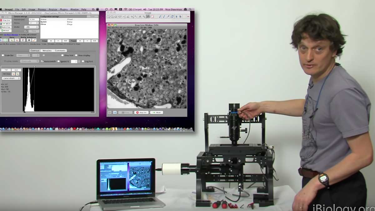
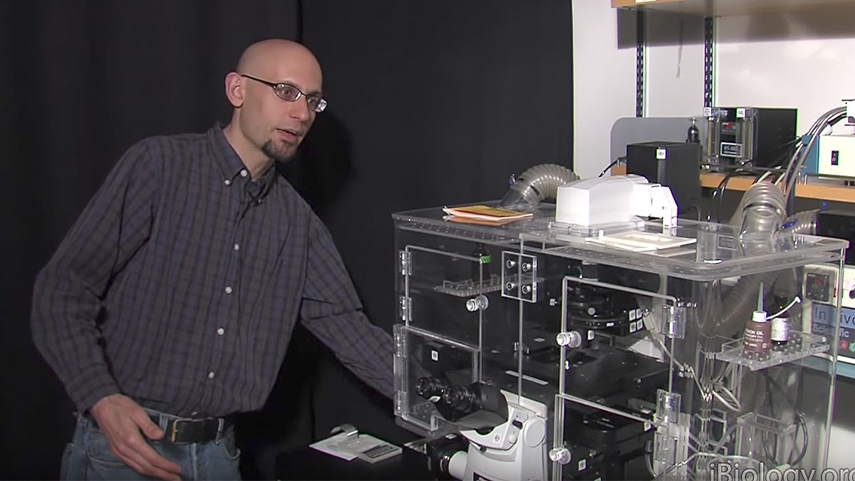
Taking apart a microscope helps you discover all the important optical components and get a better understanding of how things work. It is not always practical to do this yourself, therefore, have a look at this video to see the internals of the Nikon Ti Eclipse microscope.

Questions

  1. The fluorescence aperture diaphragm:
    1. Attenuates the intensity of illumination
    2. Unlike the condenser diaphragm for transmitted light, fluorescence aperture adjustment does not affect resolution
    3. Is conjugate with the specimen
    4. A and B
    5. A, B and C
  2. True or False. The flange focal distance in an ISO C-mount is standardized so that the primary image plane is located at the camera detector.
  3. Which of the following are components of the optical nose piece in this Nikon microscope
    1. Objective lens
    2. An infrared laser diode for automated focusing
    3. DIC prisms
    4. The Bertrand lens
    5. A and B
    6. A, B and C
    7. A, B, C and D
  4. The field diaphragm in the fluorescence light path
    1. Is a good location for focusing a laser beam for creating an intense spot of illumination for FRAP (fluorescence recovery after photobleaching)
    2. Is conjugate with the back focal plane of the condenser
    3. Is typically located deep within the body of the microscope
    4. Can be shifted in the optical light path by adjustment with a slider

Answers

View Answers
  1. D
  2. True
  3. F
  4. A

Speaker Bio

Steve Ross

Steve Ross

Stephen Ross is the General Manager of Product and Marketing at Nikon Instruments.  He is also very involved in teaching microscopy at the Marine Biological Laboratory in Woods Hole and at the Bangalore Microscopy Course at the National Centre for Biological Sciences. Continue Reading

Playlist: Microscopy Series

  • Steven Chu
    Pushing the Boundaries of Light Microscopy
  • Nico Sturman on iBiology: Disassembling and ASI Ramm in Microscopy
    Demystifying Microscopes: Disassembling an ASI RAMM Microscope
  • Optimizing Detection of GFP
  • Microscopy: Live Cell Imaging and Environmental Control (Kurt Thorn
    Live Cell Imaging and Environmental Control

Reader Interactions

Leave a Reply Cancel reply

Your email address will not be published. Required fields are marked *

Primary Sidebar

Like our Website?

You'll love our newsletter...

  • Sign up for:
    • Exclusive iBiology content
    • 10 Must See Biology Videos
    • Talks by 20+ Nobel Winners
    • Our young Scientist Survival Toolkit
    • Talks by trailblazing Women in Biology
    • Updates on exciting iBiology projects in development
    Tyler Allen
  • This field is for validation purposes and should be left unchanged.

Privacy Policy

Help us keep bringing the world’s best biology to you!

Footer

Funders

National Science Foundation: NSF
Lasker Foundation
NIGMS

Partners

EMBL
EMBO
HHMI
NRMN
UCSF

Start Here

  • Talks for Everyone
  • Talks for Students
  • Talks for Research
  • Talks for Educators

Explore

  • Explore
  • All Playlists
  • All Speakers
  • All Talks

Talks By Topic

  • Biochemistry
  • Bioengineering
  • Biophysics
  • Cell Biology
  • Development and Stem Cells
  • Ecology
  • Genetics and Gene Regulation
  • Human Disease
  • Immunology
  • Microbiology
  • Neuroscience
  • Plant Biology
  • Techniques

Talks by Series

  • Bench to Bedside
  • Famous Discoveries
  • Great Questions
  • Share Your Research Series

Career

  • Professional Development
  • Career Exploration
  • NRMN Resources
  • Biomedical Workforce

Courses

  • Microscopy Series
  • Short Microscopy Series
  • Open edX Courses
  • Cell Biology Flipped Course
  • Engineering Life Flipped Course
  • Evolution Flipped Course

Educator

  • Educator Registration
  • Educator Resources
  • Log In

About Us

  • About Us
  • iBiology Team
  • Wonder Collaborative
  • Contact Us
  • Mission
  • Privacy Policy
  • SCL Financial Conflict of Interest Policy

This material is based upon work supported by the National Science Foundation and the National Institute of General Medical Sciences under Grant No. 2122350 and 1 R25 GM139147. Any opinion, finding, conclusion, or recommendation expressed in these videos are solely those of the speakers and do not necessarily represent the views of the Science Communication Lab/iBiology, the National Science Foundation, the National Institutes of Health, or other Science Communication Lab funders.

© 2022 - 2006 iBiology · All content under CC BY-NC-ND 3.0 license · Privacy Policy · Terms of Use · Usage Policy
 

Power by iBiology